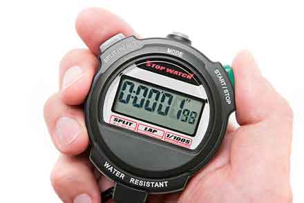
Basically, a timer is a mechanical device that can be used to measure the duration of an event. It can be a watchdog timer, a retentive on-delay timer, or a split-timer.
Electromechanical cam timer

Typically used in industrial settings, the Electromechanical Cam Timer is a mechanical device that uses electricity to control a series of switches. These devices are commonly found in industrial appliances, such as washers and driers.
The Electromechanical Cam Timer is a complex system combining electrical and mechanical components. It can be a simple unit that includes a single cam, or a larger more complex one that can contain as many as 12 cams. It is usually powered by a synchronous motor, and can be controlled by a switch or a controller.
The main purpose of an Electromechanical Cam Timer is to start and stop machines at a predetermined interval. This can be achieved by turning a wheel, or by sending control signals to valves.
These devices were once widely used in industrial applications, but are now being replaced by programmable logic controllers (PLCs) and microprocessors. These systems are more sophisticated, with more features, better feedback, and a greater ability to adapt to changes in the environment.
Watchdog timer
Using a watchdog timer is an excellent way to ensure your computer is in working order. The watchdog is an important component of many microcontrollers. It helps your system recover from transient failures. It can also detect when your MCU is malfunctioning and resets the device.
When the clock ticks for 2000 times, the counter is reset. This may sound like a simple task, but it’s actually pretty complicated. The hardware and software must work together to determine when a watchdog counter is overdue.
The counter is compared to a timeout value that is loaded into the comparator. If the value is lower than the timeout value, the counter continues to count. However, if the value is higher than the timeout value, the counter stops counting.
Normally, a microcontroller will initialize the watchdog and begin counting when the program boots up. However, it’s not always possible. This is especially true in cases where the program takes a long time to finish, check out the post right here.
Retentive on-delay timer
Unlike the nonretentive timer, the retentive timer will accumulate the running time for a motor or other device when the power is on. In the event of power loss, the accumulated value is reset to zero. However, when a retentive timer is de-energized, the value will retain unless an instruction is used to disable it.
Retentive timers have three useful status bits: a Timer Done bit (DN), an Enable bit (EN), and a Timer Timing bit (TT). These three status bits are essential for programming a retentive on-delay timer.
The Timer Timing bit is HIGH when rung conditions are true and low when they are false. The auxiliary bits are HIGH when “Accum” equals “Preset” and when the counted time base intervals are reached.
The DN bit is ON when the accumulator is counting. When input A is turned off, the DN bit is off. Similarly, the TT bit is ON when the rung condition is true and low when it is false.
Split-timer mode
Depending on the application, a timer can be programmed to be in various modes. These modes can be set using a combination of the M1 and M0 bits in the TMOD register.
The M0 bit determines whether the timer is a counter or a timer. In the case of a counter, the second flip-flop divides the frequency of the clock by 2. In the case of a timer, the second flip-flop counts the number of timer pulses since the timer started. In the case of a timer, this count is incremented by the value in the Timer Count registers (TH).
In the case of a timer, when the count is less than zero, the timer interrupt flag TF1 is set. When the count rolls over to all 0s, the timer flag TF0 is set.
Summary:
In the case of a timer, if the count is greater than 255, the timer will reset to the THx value. The THx value is then loaded into the timer low byte (TLx) as a prescaler.


 Tips and Tricks to Help You Beat 2048